DEFINITY Enterprise Communications Server Release 5
Maintenance and Test for R5vs/si
555-230-123
Issue 1
April 1997
Maintenance Object Repair Procedures
Page 10-486DIG-LINE (Digital Line)
10
Digital Line Electronic Power Feed/Positive
Temperature Coefficient/PPF Test(#11)
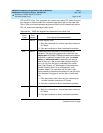
For TN413, and TN754 vintage 13 or earlier, this is an Electronic Power Feed
(EPF) restoral test. In this test, the processor requests that the EPF be turned on
for a given port, and an attempt is made to turn on the power supply to the
station. If no current is drawn, the station is probably not connected. If an
overcurrent condition is sensed, there may be a short in the loop. A message is
returned reporting that either the EPF was successfully turned on, or that an
overcurrent condition was sensed. This test is repeated again 5 seconds later.
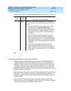
For TN754 vintage 14 or later, TN754B and TN2136 this is a Positive Temperature
Coefficient (PTC) restoral test. In this test, the processor requests that the PTC be
turned on for a given port, and an attempt is made to turn on the power supply to
the station. If an overcurrent condition is sensed, there is probably a short on the
power line that causing the PTC to open and disconnect the voice terminal. Since
the PTC does not have self-restoral capability, the voice terminal must be
manually unplugged for 30 seconds and then plugged back in to restore the
PTC. A message is returned reporting that either the PTC was successfully
turned on successfully with no problem or an overcurrent condition was sensed.
This test is repeated again 5 seconds later.
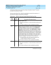
TN2181 and TN2224 boards carry a Protected Power Feed (PPF) relays, one for
each port. Therefore this will be a Protected Power Feed restoral test. The test
procedure and its response is same as that of EPF. One of differences between
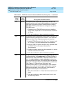
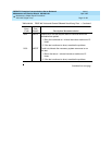
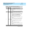
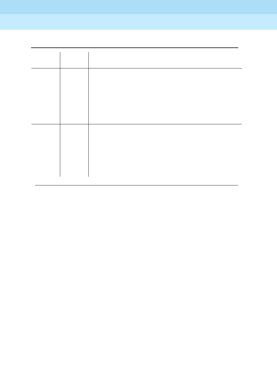
1
2
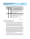
FAIL The Network Processing Element (NPE) of the tested
port was found to be transmitting in error. This will cause
noisy and unreliable connections. Failure code 1
indicates that the Crosstalk test failed on the primary
channel. Failure code 2 indicates that the Crosstalk test
failed on the secondary channel.
1. Replace circuit pack.
PASS The port is correctly using its allocated time slots.
1. To be sure that this is not an intermittent problem,
repeat this test up to a maximum of 10 times to make
sure it continues to pass.
2. If complaints persist, examine the station,
connections, and wiring.
Table 10-130. TEST #9 Digital Line NPE Crosstalk Test — Continued
Error
Code
Test
Result Description/ Recommendation
Continued on next page


