DEFINITY Enterprise Communications Server Release 5
Maintenance and Test for R5vs/si
555-230-123
Issue 1
April 1997
Maintenance Commands and Trouble-Clearing Aids
Page 8-108display communication-interface
8
Output for Hop-channels qualifier
The number of the local processor channel used to hop the interface link
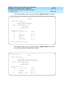
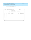
channels is not shown. The following display shows a typical result when display
comm hop is entered.
Output for Links Object
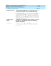
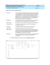
Link/Channel A Identifies the first of the two link/channels joined by the hop
channel. Links range from 1 to 16, channels from 1 to 64. The
link/channel must not be assigned to a local processor channel,
and the link must not be assigned to a PRI local processor
channel.
Link/Channel B Identifies the second of the two link/channels joined by the hop
channel. Links range from 1 to 16, channels from 1 to 64. The
link/channel pair must not be assigned to a local processor
channel, and the link must not be assigned to a PRI local
processor channel.
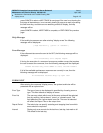
Link The physical link number.
Enabled "Yes" indicates the link is enabled for normal operation. ”No,” the
default, indicates that message flow over the link is suppressed.
The link can only be enabled if the corresponding data module
has been administered.
X.25 Extension The extension of the TN577 Packet Gateway port through which
the link is routed.
Destination Number "External" indicates the link goes to equipment connected
locally to an external port on a Packet Gateway circuit pack.
Such ports must show a "y" in the Establish Connection field.
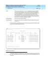
display communication-interface hop-channels Page 1 of 4
HOP CHANNEL ASSIGNMENT
Link/Channel A Link/Channel B Link/Channel A Link/Channel B
3 1 4 12


